Here i share my Engineering Project with you. Its time get in now to fly and caputre pics of glorious earth to transfer power for energising this green land.
ABSTRACT
Wireless magnetic resonant power transfer is an emerging technology that has many advantages over other wireless power transfer methods due to its safety, lack of impedance, and efficiency at medium ranges. Power is generated by wireless magnetic resonant power system which is fixed to unmanned aerial vehicle (UAV) to provide power or to recharge batteries of wireless sensors and other electronics far removed from the electric grid. As to increase the amount of power transfer the UAV is controlled by knowing the load’s axis where to maintain the axis of UAV and load with each other. Image processing technique is used to find the axis of the ground load to establish maximum resonance for maximum power transfer. On grasping of ground load images as frames we could get the inclination of UAV with respective to the axis of the ground load. This enable us for better control of UAV. This system can be used to transfer power where connection to electrical grid is not feasible.
INTRODUCTION
Electricity and its power transmission from one place to another is one of the vital roles in day today life. It’s very essential in science and technology; still the researches are going on to transfer power from one end to another end. Scientists use different methodologies (modes) to transfer power via microwaves; laser, induction coupling, magnetic resonance induction coupling and still the technologies are emerging to increase the efficiency to reduce the losses. Based on this modes of transmission; we want to give a solution for this. So here we transmit power from Unmanned Aerial Vehicle (UAV) to ground loads (sensors, LED’S, batteries) which are far away from the electric grid with greater efficiency. Here we use magnetic resonance induction coupling to increase the range of power transfer.
The principle used is Magnetic Resonance Induction Coupling. Inductive coupling works on the principle of electromagnetism. When a wire is proximity to a magnetic field, it induces a magnetic field in that wire. Transferring energy between wires through magnetic fields is inductive coupling. Magnetic resonant coupling uses the same principles as inductive coupling, but it uses resonance to increase the range at which the energy transfer can efficiently take place. Since the transmission is based on resonance, maximum resonance has to be maintained for maximum power transfer. The system consists of resonant power source, a resonant power capture device, a portable battery which is carried by UAV and a resonant repeater that boosts the oscillating magnetic field. For establishing maximum resonance and to increase the efficiency Image Processing technique is used. In image processing the ground load image is processed to find the axis. Using this parameter Unmanned Aerial vehicle can be positioned exactly to match both the ground load and copter axis.
The Major contributions provided hare are 1) Making a resonant power transfer system which can be implemented and operated from a Unmanned aerial vehicle, 2) As along using image processing technique for optimization of power transfer, and 3) Experimentally demonstrating the ability to transfer power to loads located in ground. Observations from image processing technique suggest the possibility of being able to use feedback to generate an autonomous controller for finding and optimizing proximity to the sensor node for power transfer.
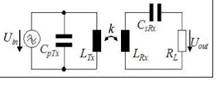
Magnetic resonance induction coupling: Inductive Power transmission are enhanced by resonant circuits. In a system with low coupling factor, where resonant circuit can give good efficiency of power transmission. The resonator in the receiver end consists of the inductance coil and a capacitor. The transmitter end can also have a resonator. The common circuit diagram is shown in Figure 1. The resonant capacitors terminates the stray inductance in the receiver and the magnetizing inductance in the transmitter (Tx).
The only limit for the power transmission now is the winding resistances of the coils, which impedance is less range of magnitude lower than that of the inductance. Finally, for a given source, much more power can be received. Inductive coupling also has good efficiency and power transfer over short distances, but generally the transmission of energy diminishes at a rate of 1/x3 as distance increases.
Wireless power transmission system: Wireless power transmission can achieved very easily, but obtaining good efficiency is really matters. This can be done by having needed quality factor and coupling factor and it is even better to consider transmitter coil(Tx) and receiver coil(Rx) structures.
A. Quality factor: The ratio of the inductance L to the resistance R of a coil remains same for different winding arrangements in the same volume and shape. The quality factor express how well a resonant coil can hold energy without losses to heat. The formal definition of quality factor is the ratio of apparent power to the power losses in a device.
B. Coupling factor: Coupling factor rely upon distance between the transmit(Tx) and receive coils(Rx), only a small amount of the magnetic flux is generated by the transmitter coil will penetrates the receiver coil and contributes to the power transmission. When the Receiver gets more flux then it has better coupling effect. The coupling is expressed by the coupling factor k.
The range of coupling factor is between 0 and 1. Where one expresses perfect coupling, i.e. Flux generated by Tx coil is completely received by the Rx coil. The Zero shows that where transmitter (Tx) and receiver coils(Rx) are not in axis to one another. The coupling factor(k) is determined by the gap between the inductors and their respective size. Coupling factor is also determined by the structure of the coils and the inclinations between them. Moving of transmitter coil from its axis causes a decrease of k. Figure 2 will describe this effect for an ideal arrangement of planar coils. It shows the measured and calculated coupling factor at different inclinations and different distances among coils. The range between 0.3 to 0.6 are well enough for good coupling factor. It is also to be noted that negative coupling factor means that the receiver captures the magnetic flux below the coil.
The value of Q can have between zero to infinity, but it is tough to get values far above thousand for coils. For big production we may obtain values around hundred. A quality factor should not be less than ten. These are to be considered as the typical values of magnitude. For a constant operating frequency, the Q factor is mainly dependent on the structures of the coil as well as the materials used.
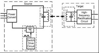
Circuit diagram for wireless power transmission based on principle of wireless power transmission is shown in Figure 3.
By maintaining good Quality factor and Coupling factor the structure of transmitter coil and receiver coil design is shown in Figure 4.

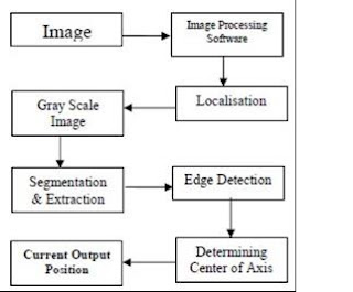
Finding inclinations using image processing:The transmitter coil which is fixed in UAV has to maintain its position at the axis with respective to the receiver where this alignment has to be kept fixed with slight movements are allowable because UAV cannot be stabilized at particular position so moving up or down a inch will affect only a minute change in power transfer. On working in remote areas where we should know the exact location and position of load for controlling UAV. Unmanned Aerial Vehicle can be controlled by wireless remote communication but for achieving more precision, image processing technique is used through MATLAB. The load image is taken as live video which has to be transmitted to controller (i.e)CPU. The received video is converted as frames and every frame has to be processed with image processing software. On using certain algorithm for finding center of axis of load (receiver) with respective to the transmitter coil(Tx), where this gives the amount of inclination of transmitter which is fixed in UAV.

With obtained output inclination on MATLAB, the UAV can be controlled to desired position. This process happens at every instant until the both transmitter and receiver axis are matched with eachother. At the time of perfect match of axis the output is indicated as “axis matched”.
Steps for Finding Center of Axis: Received Frames are converted as series of images and loaded to image processing software. Loaded images are converted to gray scale image where image is segmented in parts and edges are detected this gives histogram of variance from histogram the amount of inclinations is found.
According to the algorithm for finding center of axis
• If obtained output value of inclination is greater 210 then center of axis is matched.
• If obtained output value of inclination is greater than60 and less than 100 then center of axis is inclined Bottom.
• If the output value of inclination is less than 50 then center of axis is inclined Top.
• If the output value of inclination is greater than 100 and less than 150 then center of axis is inclined Left.
• If the output value of inclination is greater than 150 and less than 200 then center of axis is inclined Right.
• Apart from this range any other values gives the output as out of range.
The output indicated will enable us to know the current position of the UAV with respective to Receiver coil. From this output we can make our UAV to be control our in perfect alignment till the power transfer process happens.
Analysis of wireless power transfer system
A. Current Vs Distance Graph: In Current vs Distance Curve of Figure 5 we come know that current decreases as the distance increase which denotes that induced emf gets decreased as the gap between the transmitter and receiver increased. Current is inversely proportional to distance.


Voltage Vs Distance Graph: In Voltage Vs Distance Curve of Figure 6 we can see that voltage is constant this is because the rectified voltage received is passed through voltage Regulator which makes the output to flow at constant rate.The amount of power transfer will P=V.I where the maximum of 5W of energy is transmitted. This may vary as the with the small amount of change in distance of UAV. So the 2% of error is tollarable.
CONCLUSION AND FUTURE WORKS
On considering usual wired power system where we could get output with maximum efficiency but in this, the critical case when transferring power to long remote areas where wireless power transfer systems arise but comparatively the efficiency depends on how well the coils of transmitter and receiver are coupled with each other. In this system we obtained maximum of 5W where this could be enhanced in many ways in future. Increasing the thickness of the coil and number turns of the coil will tend easily to increase the amount of power transfer. By placing the meta material slab between the transmitter coil and receiver coil will be increasing the output without changing the size of transmitter and receiver system.
For full project report, add mail Id as comment below. You quires can be clarified through comments and I am so glad to hear your sparkling ideas for further enhancements in projects so kindly share your comments.
REFERENCES
N. Tesla, “Apparatus for transmitting electrical energy,” Patent US 1 119 732, Dec. 1, 1914.
A. Kurs, A. Karalis, R. Moffatt, J.D.Joannopoulos, P.Fisher, and M. Soljai, “Wireless power transfer via strongly coupled magnetic resonances,” Science, vol. 317, no. 5834, pp. 83–86, 2007.
WiTricity Corp. — Applications of WiTricity Technology, www.witricity.com/pages/application.html
Power play: Wireless Charging at a distance arrives, http://www.computerworld.com/s/article/923295 3/Power_pl ay_Wireless_charging_at_a_distance_arrives
A. Sample, D. Meyer, and J. Smith, “Analysis, experimental results, and range adaptation of magnetically coupled resonators for wireless power transfer,” Industrial Electronics, IEEE Transactions on, vol. 58, no. 2, pp. 544 – 554, feb. 2011.
Vinoth kumar, Wireless Energy Transfer Possibility, http://thinkquestprojects.blogspot.in/2012/01/wir elessenergytransfer- possibility.html


